
There are also twenty 4-tap combinations, twenty-eight 6-tap combinations, and ten 8-tap combinations that satisfy the maximal-length criteria. For example, in the case of a 10-bit LFSR, there are two 2-tap combinations that result in a maximal-length sequence: and. As was previously noted, alternative tap combinations may also yield maximum-length LFSRs, although the resulting sequences will vary. Taps for maximal length LFSRs with 2 to 32 bits.The taps are identical for both XOR-based and XNOR-based LFSRs, although the resulting sequence will of course differ. These values are presented for your delectation and delight in Fig 4 (the * annotations indicate sequences whose length is a prime number).Ĥ. The author created a simple C program to determine the taps for maximal-length LFSRs with 2 to 32 bits. The problem is weeding out the ones that do from the ones that don’t, because badly chosen taps can result in the register entering a loop comprising only a limited number of states. Figure below shows the maximum length sequence produced by a 4 bit LFSR.Each LFSR supports a number of tap combinations that will generate maximal-length sequences.

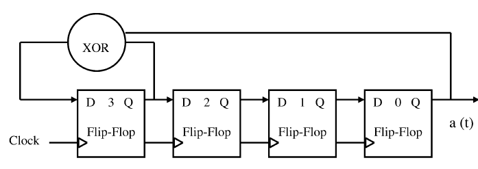
For a small LFSR like the present one (4bit) its easy to identify the Taps to the XOR gate which can produce maximum length output but just imagine how can we identify the Taps for the XOR if the number of bits is 10bits ? Obviously we cant go by BRUTE FORCE method by trying all possible combination to identify the Taps which will produce maximum length sequence. In our example if the LFSR has to be of maximum length then the pattern has to repeat after 16(2^4) clock cycles. By maximum length we mean that the pattern must repeat itself after 2^N clock cycles for a N bit LFSR. But the pattern has to be of maximum length . There is no such order from where the inputs to the XOR comes from to produce a random pattern. So from the figure above the Taps are 0 and 3 FF's. The inputs to the XOR are called the Taps. This is a general structure for a 4 bit LFSR. When we take out the output of these FF they will have a random pattern. This XOR operation introduces a new bit into the shift register. But the only change is that the input to the first (D3 in th figure) is from the XOR of the o/p from FF's 0 and 3 (from fig). It consist of D-FF connected in cascade as shown with the same clock applied to all the FF to make them act like a shift register.


 0 kommentar(er)
